
Basic working of double voltage step up converter circuit using TDA2822 Computer Basic, Hobby
What is Boost Converter? A boost converter is basically a step-up chopper or step-up dc-to-dc converter by which we can obtain an output voltage greater than the input voltage. In other words, boost converters are regulator circuits that generate a voltage at the output side whose magnitude will be greater than or equal to the input applied voltage.

DC stepup converter schematic Download Scientific Diagram
A look into how boost converters work in a very visual format. Try this circuit: http://goo.gl/nkHq9HBoost Converter Wiki: https://en.wikipedia.org/wiki/Boos.
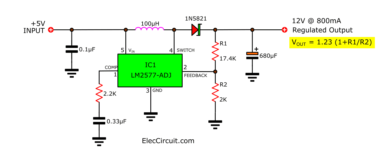
LM2577 Boost Converter circuit Step up Datasheet Pinout
This step-up conversion in the boost converter is achieved by storing energy in the inductor and releasing it to the load at a higher voltage. Boost converters are widely used in battery-powered devices where perhaps a pair of batteries deliver 3V but need to supply a 5V circuit.
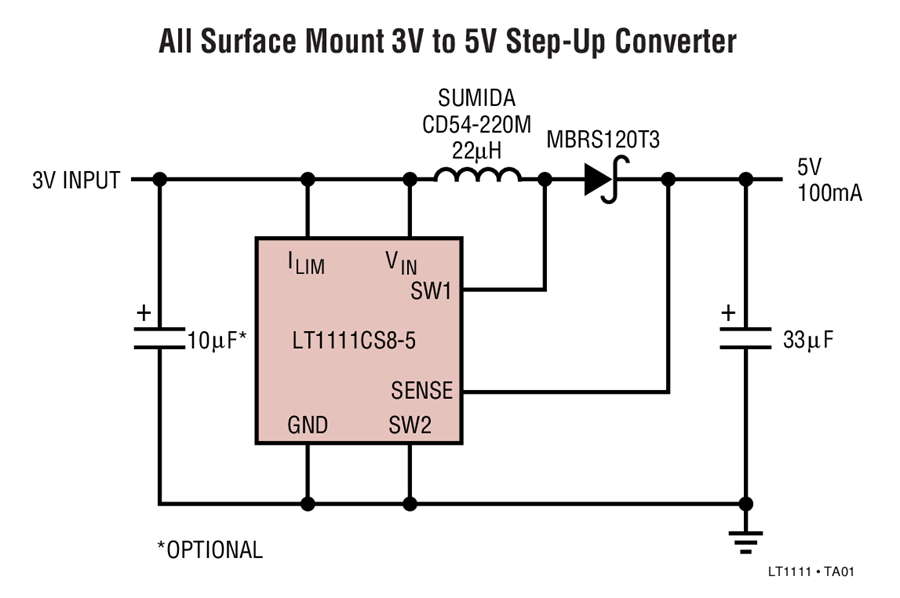
LT1111 3V to 5V StepUp Converter Circuit Collection Analog Devices
A DC boost converter circuit is designed for stepping-up or boosting a small input voltage levels to a desired higher output voltage level, hence the name "boost" converter. Since these circuits basically step up a low voltage to a higher voltage levels, they are also know as step-up converters.
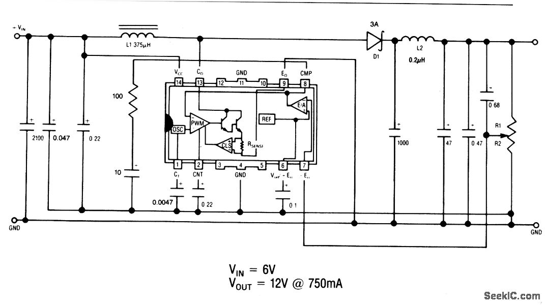
Adjustable_dc_dc_step_up_converter_750_mnA Power_Supply_Circuit Circuit Diagram
What is a boost converter? This article discusses key initial design tasks for a step-up voltage regulator and describes its structure. In my last article series, LTspice helped us to examine the features of a step-down switching regulator's power stage.
Stepup converter 3.3V to 5V x 175mA MC34063 Multisim Live
The SEPIC is a step-up/step-down DC-DC converter. This level of flexibility isn't really needed in a purely step-up application, but the SEPIC has built-in short circuit protection. See figure 4, a simplified schematic of a SEPIC converter. If V OUT is grounded, the blocking capacitor allows only AC current to be conducted to the output.
DC to DC Boost (Step up) Converter Circuit using UC3843
Step 1: Watch the Video! The video gives you all the information you need to create your own boost converter. The next steps just contain additional information for your convenience. Ask Question Step 2: Order Your Components! Here is a list of all the parts that you need with example sellers (affiliate links): Aliexpress:
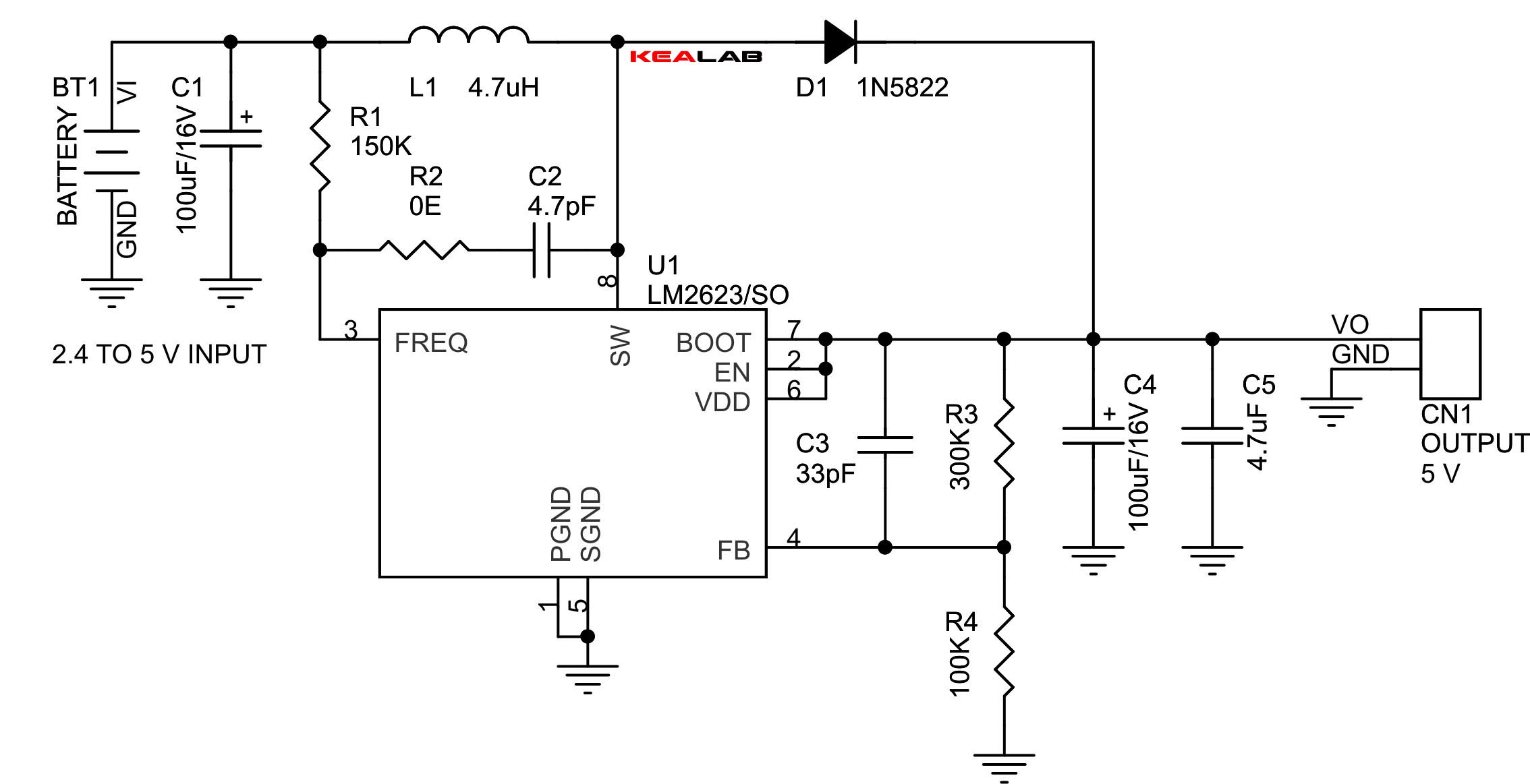
2.4V to 5V Step Up DCDC Converter
Boost Converter | Step Up Chopper May 23, 2021 by Electrical4U DC-DC converters are also known as Choppers. Here we will have a look at the Step Up Chopper or Boost converter which increases the input DC voltage to a specified DC output voltage. A typical Boost converter is shown below. The input voltage source is connected to an inductor.
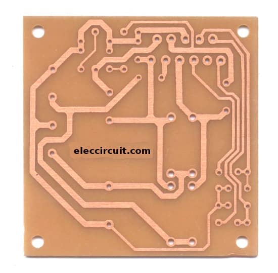
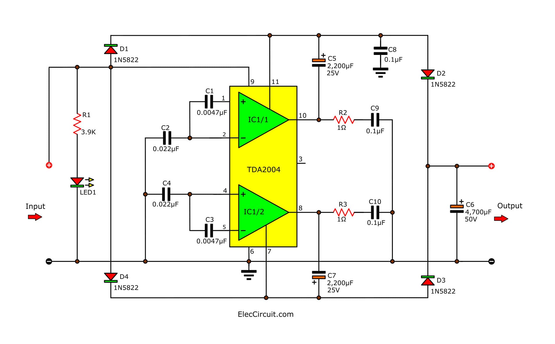
Simple 12V to 24V step up converter circuit using TDA2004 ElecCircuit
A Step-Up converter is capable of boosting a low input voltage, say 1.5 V to a much higher voltage like, 5 V. Since, Power must be conserved, while boosting the voltage, output current is lowered. We take a look at the steps followed by all the necessary calculations to design a Step Up DC-to-DC Boost Converter. Ask Question Comment
USB 5v to 12v dcdc stepup converter circuit
Figure 1a-1c. These high-voltage DC-DC converters in three topologies are used to create high output voltage from low input voltage. The high-voltage bias required in many APD applications (75V) is derived from a 3V supply. That requirement presents the following challenges: High-voltage MOSFETs generally do not operate with a low 3V gate drive.
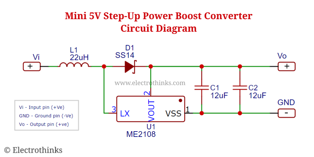
DCDC Mini 5V StepUp Power Boost Converter Module Electrothinks
A step-up converter, also called a boost, is a DC-DC power converter that increases the input voltage and provides a higher output voltage. The switching circuit consists of an electronic switch (a BJT, MOSFET or other) that alternately switches ON and OFF at a very high frequency (see general circuit diagram in Figure 1 ).
Ac To Dc Convert Circuit Diagram
High Power DC to DC Step up Boost Converter Circuit👉Get a free trial of Altium Designer with 365 and 25% off your purchase :👉 http://www.altium.com/yt/ZAFE.
Step_up_converter_with_adjustable_output Power_Supply_Circuit Circuit Diagram
A boost converter or step-up converter aids in stepping up a DC voltage from the input to the output. The conduction state of the switch dictates the operation of the circuit. During the on-state, the current flowing through the inductor increases linearly. The diode is not conducting. This is shown in Figure 2.

Simple 12V to 24V step up converter circuit using TDA2004 ElecCircuit
In this article, we'll use the same circuit to explore the electrical behavior that makes step-up conversion possible. The Switch-On State. As with the buck converter, the boost converter has two fundamental operational states: one when the power switch is closed (the switch-on state), and one when it is open (the switch-off state).
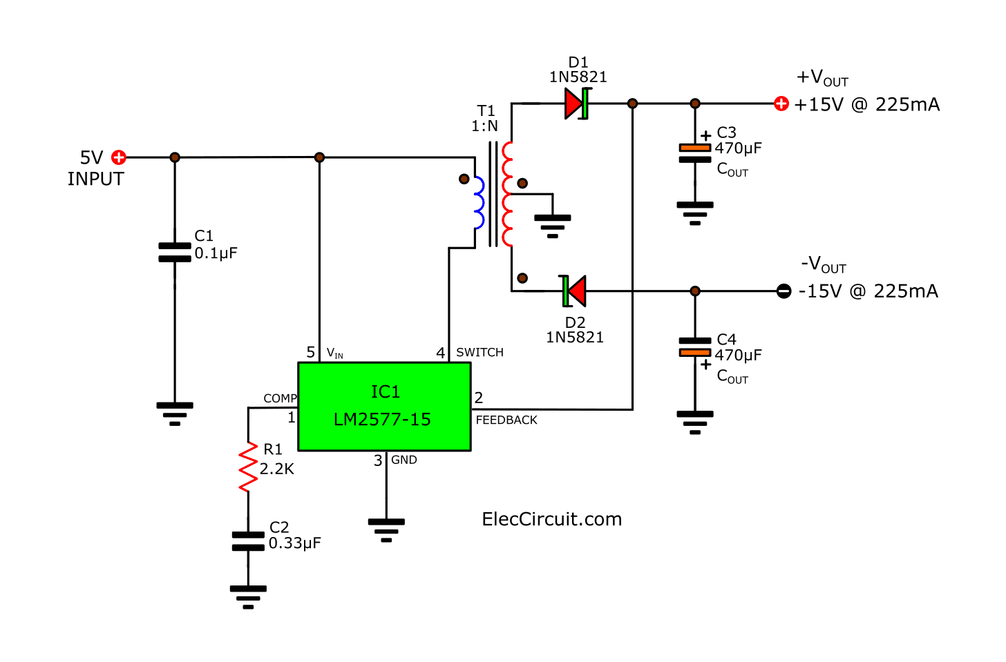
LM2577 Boost Converter circuit Step up Datasheet Pinout
The basic components of the switching circuit can be rearranged to form a step-down (buck) converter, a step-up (boost) converter, or an inverter (flyback). These designs are shown in Figures 1, 2, 3, and 4 respectively, where Figures 3 and 4 are the same except for the transformer and the diode polarity. Feedback and control circuitry can be.

USB 5V to 12V DCDC StepUp Converter circuit EasyEDA open source hardware lab
A boost converter (step-up converter) is a DC-to-DC power converter that steps up voltage (while stepping down current) from its input (supply) to its output (load).